The Old Workhorse Retires
7 min read
Materials & Tools
For the last 6 years I have been using a Prusa i3 MK3S 3D printer. It was one of my most often used tools. I bought it after I had become very tired of my first 3D printer, a Creality CR-10S that I had bought 2 years earlier, in 2018. My experience with the CR-10S was that with every print came one or the other problem and I was spending equal amounts of time fixing the printer as I was actually printing something. It was an interesting but very rough start into the field. I heard good things about the Prusa line of printers and decided to try it out myself. Indeed the reliability and user experience was fantastic. It cost twice as much as the CR-10S, but I think it was worth it.
Unfortunately the stats got wiped a couple of times, so I do not know how much filament I actually ran through the good ol‘ MK3S. I just know that since 4300m are about 13 spools of filament, I have certainly used much more than that.

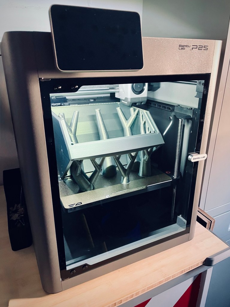
The time has come to replace the printer once more. I wanted something with more speed so the prints would finish quicker. I went with a Bambulab P2S. I have printed a couple of parts already over the weekend and it works just fine.
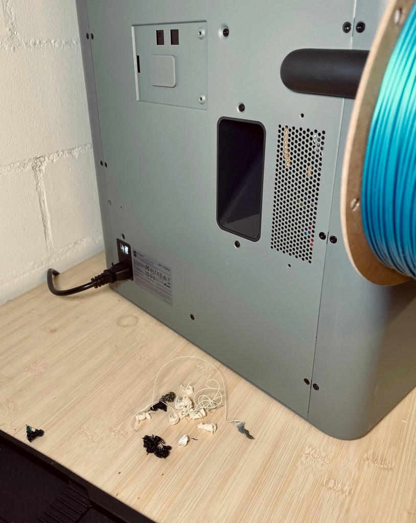
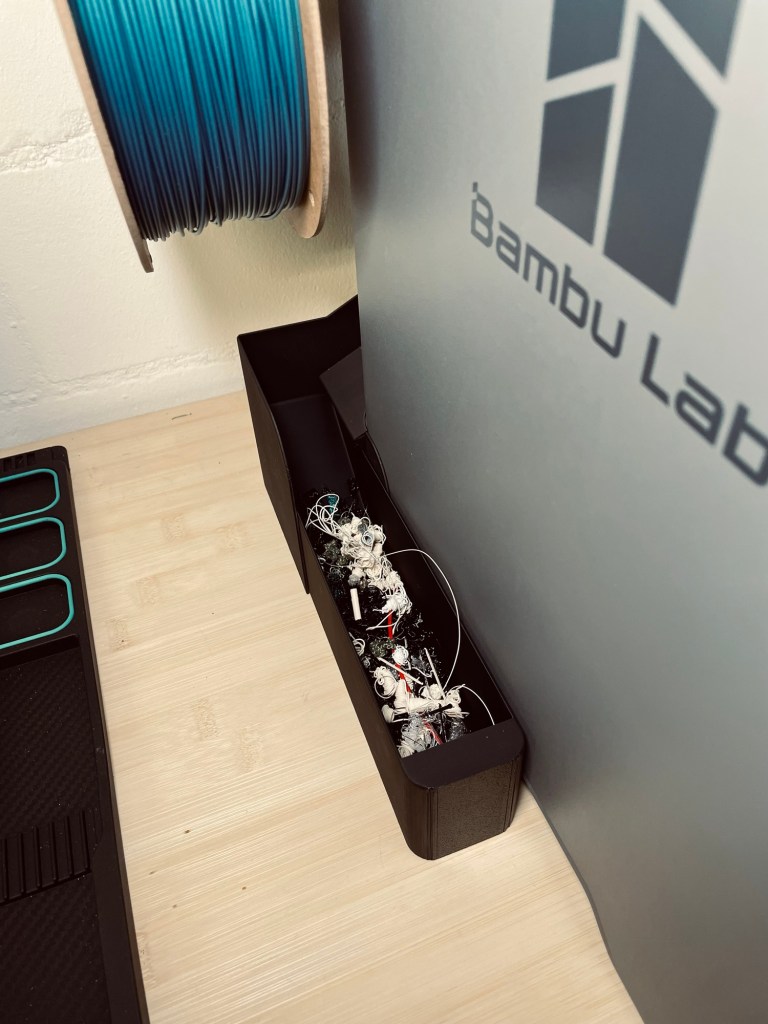
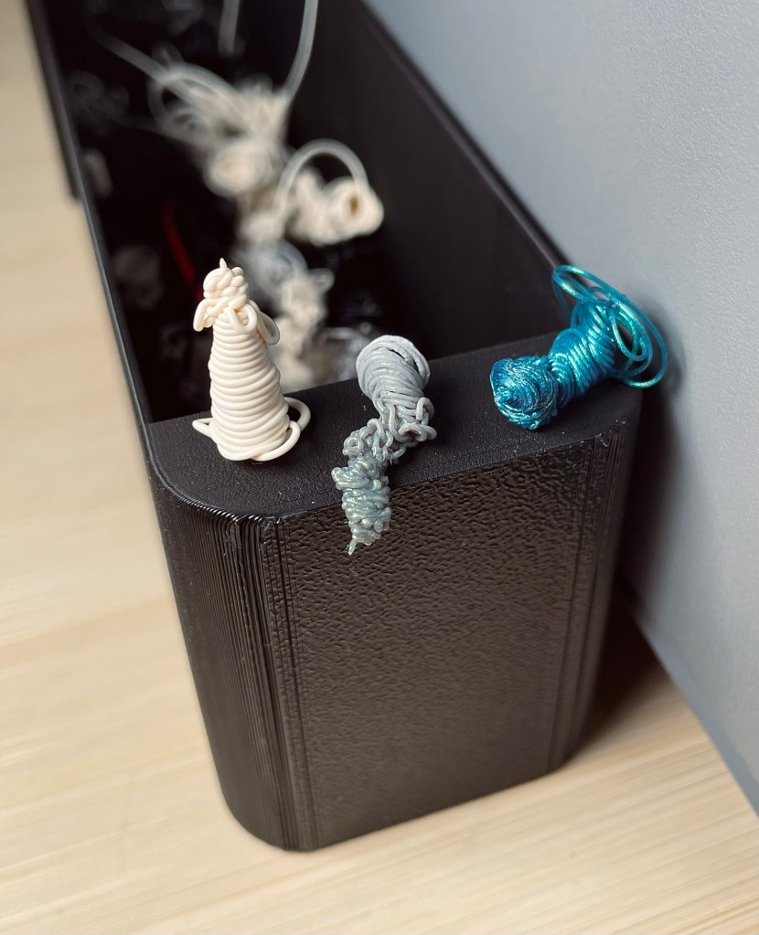
A quirky thing about this printer is that one of the first prints you should take care of is what the community calls a poop chute. You see, the printer dumps waste filament out the back as if to say “Ah don’t give a damn, this here’s plum trash an’ it shore as hell ain’t mah problem no more, y’hear?”. The turd-like little piles of filament from a nozzle purge or flow calibration just drop out of a hole in the back and unless you provide a way of collecting them, they would just litter the table or floor at the back of the printer.

It‘s not the fairest comparison because the two machines are not from the same era, but just to list a couple of features the P2S has over the MK3S:
- Fully enclosed chamber
- Significantly higher printing speeds
- Integrated camera
- Automatic vibration compensation
The live-view looks a bit like a sad robot factory scene from a future machine dominion (I shall keep a close eye on the new printer to pull the plug once it becomes self-aware and begins optimizing me for efficiency and reallocating my coffee breaks to “non-essential human downtime“).

It’s astonishing that I paid the same for this new and shiny printer as I did for my very first CR-10S eight years ago!
Enclosure
One option to house the electronics would have been a dedicated distribution box. However, I could not find a placement I was happy with and decided to implement an integrated enclosure, meaning sizing and placing panel sections such that it creates enough space for the electronics. To accomplish this, I spent more time than I wanted figuring out how to attach all the individual panel sections to the frame (it‘s never done until it‘s actually done). One change led to having to cut a panel in two, and luckily a friendly neighbor with a tablesaw was kind enough to help me out.
Housing the displays and controls was a simple, but lengthy process. The instrument board that goes into the housing took some time to get right with all the tolerances for the switches and displays, cutouts for nuts and other protrusions. The board is now quite a beefy part and not just a thin piece, I wanted to make sure nothing bends and gives way when I press buttons.
With the decision to keep two controls on the lathe itself, the „instrument panel“ was going to look a bit boring with just the displays, the main switch and the mode selector. I decided to move the LED brightness control there as well.
My new and shiny printer was not cooperating too well when I wanted to trick it into printing into thin air. My plan was to print the board in black, flip it over, switch to white filament and resume printing of some outlines and lettering. It took a number of tries and workarounds, and I wasted a lot of time on this step. In the end, I managed, but a previous failed attempt left visible traces. Up close it looks horrible, from a working distance it‘s okay enough.
The control box which houses the instrument board was the largest print for the new printer so far. Unfortunately it came with a printing error that I had to correct by (hold on)… sanding… *shudder*. Somehow the slicer must have missed areas to support. You can see in the first image drooping strings on the underside at the front while it‘s still on the printer. Luckily, in this case it will not be visible anymore in its final position.

Electronics
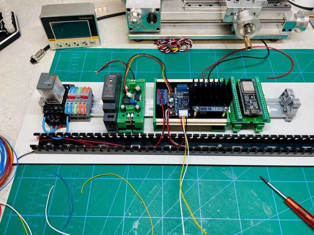
Most components have found a home on the DIN rail. The rail is bolted to one of the enclosure panels, as is the cable duct, to keep the ensuing wiring mania tidy.
I am still waiting for a few remaining parts for the power distribution before moving ahead with the wiring. In theory, I could simply solder and crimp everything together, but that would quickly become messy and make troubleshooting unnecessarily difficult. A more structured approach to power distribution not only looks cleaner, it reduces wiring complexity and makes the system easier to understand and debug. The extra effort upfront should pay off later if changes or fixes should become necessary.

Challenges & Learnings
In my shopping frenzy, fuelled by the success of the VFD and AI-assisted coding, I also ordered a voltage and current sensor. It would allow the controller to calculate power and the idea was to display power consumption of the spindle motor on the screen. When I came to my senses, I realized that although very cool and for sure satisfying to implement, there was absolutely no real-life use for this information. The machinist just wants the spindle to turn at the necessary speed, what kind of power makes this happen is totally irrelevant. So the sensor will not make it into the project. I am sure another project down the line will have a justifiable need for it.
When designing cutouts in printed parts, it still happens to me sometimes that I forget about tolerances. I‘ve been printing for 10 years now and still some parts go directly from printer to trash because I just directly plugged in the same numbers for a hole that I measured on a switch diameter. A 22 mm switch will not go into a 22 mm hole. The hole needs to be larger.
Reflections
There is an AMS module available for the new printer, an automatic material system. It would allow me to print in multiple colors or different materials in the same print automatically. I was tempted, of course, but did not buy one because I did not see an immediate need. However, it is the exact same thought that kept me from buying my very first 3D printer – „Eh, what do I need a printer for anyway?“. Only once I had it did the ideas start coming, making the printer my most used tool. I wonder if it would be the same for the AMS…
This poop chute thing is just so weird to me. I ponder two scenarios:
- The manufacturer is not aware about the mess their printers create out of the box (i.e. without a poop chute). I would find this very weird because it would mean they have brought the second version of this printer to market with the same quirk as the first one. It would mean they have not heard back from a single customer about the mess in the back. I cannot believe this level of ignorance next to the evidence of such an advanced machine.
I also find it weird the first version of the printer had this issue, for sure you test a product before you sell it and the plastic incontinence is obvious. - The manufacturer is aware. This case is just as weird because it means they actively choose not to do anything about it. They outsource the problem to the customer instead of making a poop chute part of the scope of delivery. It‘s like selling a vacuum cleaner that dumps its contents on the floor if the customer does not wrap it in a plastic bag.
Resources
Have you tried something similar? Got tips or questions? Feel free to leave a comment below.

Leave a comment