Dummy Rails Are Not Optional
6 min read
Back to the lathe again this week. There is no grand story to tie all the topics of this update together. This post simply summarizes the work done in the past weeks.
Materials & Tools
- DIN rail
- UM 72 mounting bases
- 3D printer
- Brass hex standoffs M2/M3
- Drills, threading taps, screws for mounting the DRO read heads
ESP32 DIN rail mount
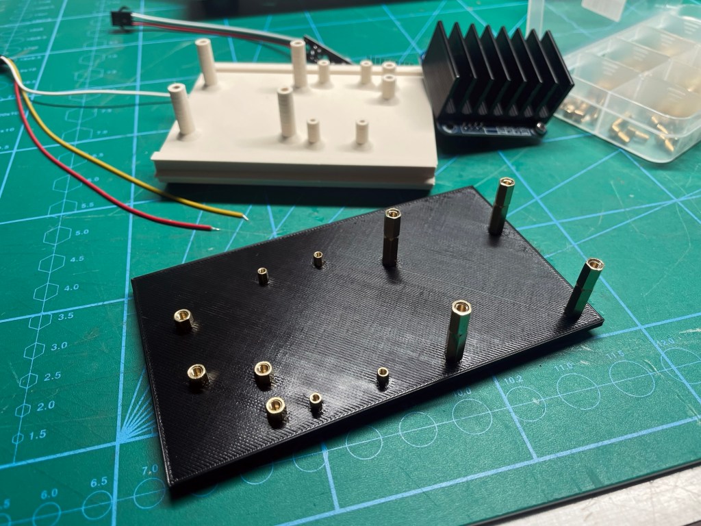
All the electronics will be mounted to a DIN rail, a useful standard to keep things tidy and organized. Not every circuit came with a DIN rail interface, but when you have a 3D printer, nothing will stop you.
Another useful „standard“ (it’s more of a commercial profile system) are UM profiles that snap onto DIN rails. I think with them the gap between DIN rail and a random accessory can be bridged nicely.
I printed a couple of versions of UM 72 inserts to take the motor driver, the RS485 converter, the RPM sensor (or what‘s left of it) and a logic level shifter. First, the mounting posts were printed as well and then I remembered that the usual brass hex standoffs would be much more fitting.
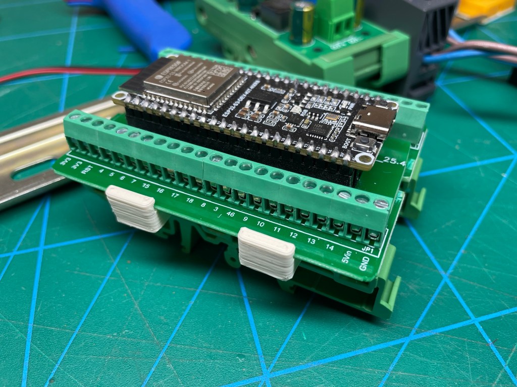
To get the ESP32 onto the DIN rail I needed a breakout board and ordered the first hit for „ESP32 breakout board“ on Ali. The punishment for this sloppy planning was the realization that the breakout board and my ESP32 were incompatible: I had ordered a 38 pin breakout board, while the ESP32 has 44 pins. Ugh. Alright, well deserved. I searched for a 44-pin variant and waited for its arrival. I present to you my next punishment:
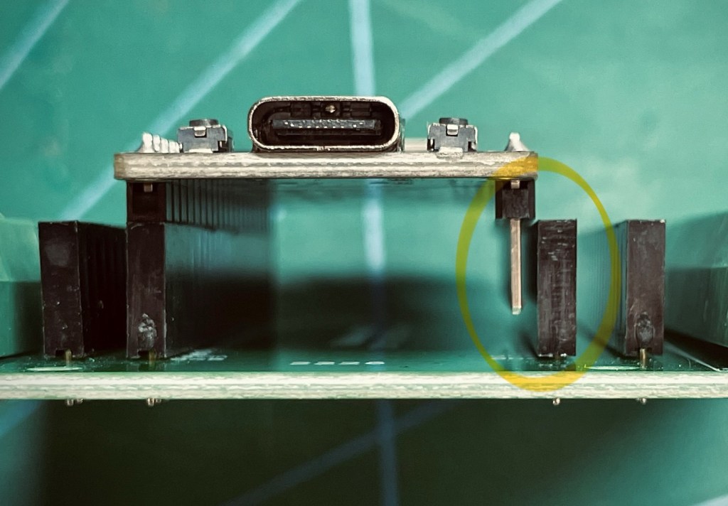
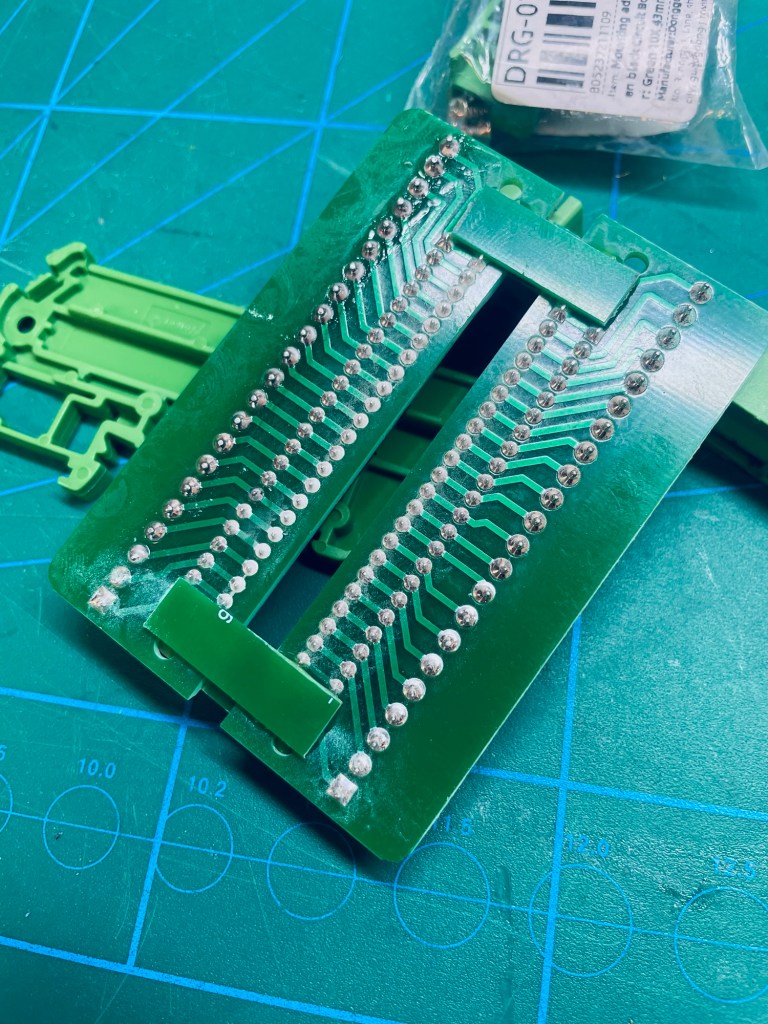
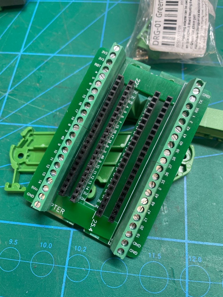
Why does Ali not magically know what mistakes I will make and send me the right stuff??? As you can see, not only does the pin count matter, but so does the board width. This time though I was done with waiting and just forced my will onto that stupid breakout board. I chopped it up and used the extra PCB material to glue it back together. Now the ESP has a lovely home on the DIN rail.
Why buy a shitty part when you can make a shitty part yourself?
DRO Read Heads
I have been procrastinating on the topic of attaching the DRO read heads for a while, but no màs, so today is the day (well, a couple of days ago, which would make it „some days ago was the day“ but then the figure of speech does not work anymore). What was so off-putting about the task? It was simply the uncertainty of how and where exactly to place the read heads.
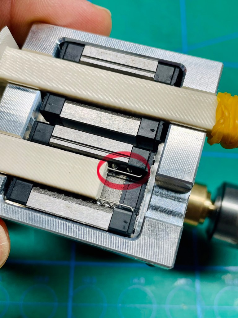
The read heads are only half the story. What they are reading is magnetism, and this comes on a tape which also needs proper placement. Both read head and tape need to be placed in such a way that:
- They experience relative movement when the axis is moved
- Their spacing remains constant
- The tape covers the full range of axis travel
- They are protected against coolant, oil, dust and metal chips
- They do not obstruct the operator
- The cables do not interfere with axis movement
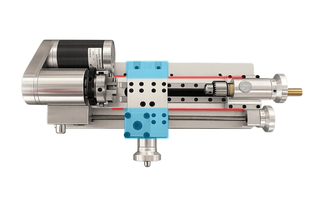
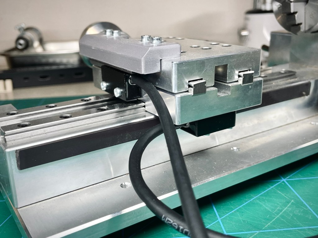
The only placement options for the Z-axis read head were either on the front or back of the main body, because the magnetic tape would not fit anywhere else (red lines in the image below). Similarly, the read head would have to go underneath the carriage, either in the front or in the back (blue areas). I preferred the cable routing on the back to have it out of my way when working and because it would be out of the way of the feed screw in front. To fit the read head, the entire carriage assembly had to come off. With great care for proper placement, I took some time to measure, drill and tap the holes.
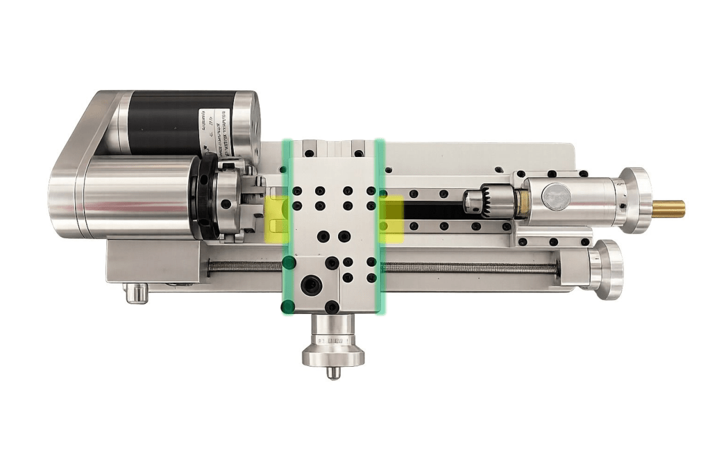
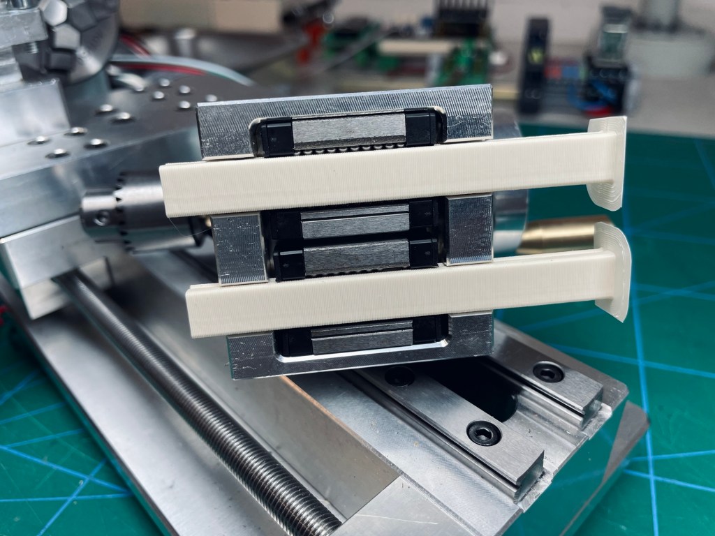
In theory, the X-axis read head could go on the left or right side of the carriage (green lines) but in practise only the right side makes sense. This way, I lose a bit of travel distance of the tailstock, but it is much better than interfering with the spindle and getting rained on by chips and cutting fluid on the left side. For the placement of the threaded holes I had much more margin of error, because any error in distance I could later easily correct with the 3D printed magnetic tape carrier. Just as long as the read head remained parallel to the magnetic tape.
Enclosure
I stretched the definition of start assembly only once I have all the parts with the frame of the enclosure. Well, I had all the parts for the frame of the enclosure. I got carried away by excitement and just put it together, even though the panels had not even been ordered yet and the way to mount them was not even decided, let alone modeled/ordered/printed. Oh well, assembly took 15 minutes (very enjoyable) and the completed frame has been waiting patiently for the next steps since then.
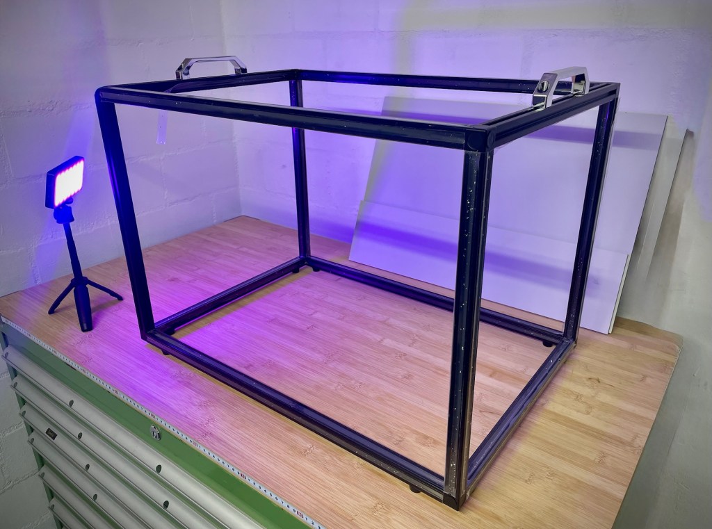
(with colourful mood lighting to distract from the bad planning)
Challenges & Learnings
When you take carriages off linear guides, always have a dummy rail ready to insert! Those balls have a real tendency to come out and they are a true pain to get back in. When it happens, using grease as a „glue“ to keep them from immediately falling out again has worked well. I lost some on the carpet when I accidentally slid the tailstock off too far. I had printed dummy rails to prevent it but slipped when dismounting the tailstock. I found four of them and managed to put them back in, phew. I‘m glad it happened on the tailstock and not on the carriage assembly which is used constantly.
Reflections
Instagram (for some strange and truly unknown reason) decided to show me ads for lathes. Proxxon to be specific. I thought it would be a great opportunity for detailed trash-talk. But in studying their lineup I may have found a good solution for a future upgrade of my lathe. So to keep it fair, I will only just say that theirs are simply much worse than mine, hehe. So what’s that good solution? Their PDE 250/E lathe comes with a quick change tool post and it is available separately. A bit pricey, as is Proxxon-fashion, but it could be a good choice of upgrade for the future.
The enclosure gave me a lot to think about. When calling „Go!“ for the project, I had not yet planned every detail of it and later got stuck with the question of how exactly to mount the panels. The plan was just „aluminum extrusion frame and panels“, no more details.
Do I look at it and say „Hey, the point of a project is to figure out all the details; as long as the general plan stands, it‘s go-time“ or do I say „It does not make sense to start a project as long as I don‘t have a grip on details that I can plan for already ahead of time“. The first means I am just taking care of uncertainties in regular project work; the second means I failed a project goal. I lean towards the latter. In any case, I have no doubt I will find a decent solution and get it done.
Resources
- Proxxon FD 150/E Closest Proxxon match to mine
- Proxxon PD 250/E Larger model with the quick change tool post
Have you tried something similar? Got tips or questions? Feel free to leave a comment below.

Leave a comment