Goodbye LCARS
6 min read
„VFDs? Again?? You must be kidding me, how boring!“ is probably what you‘re saying. Fear not, it is not directly about VFDs but related. Happy?
Screen Layout
Like I promised, this post only grazes the VFD. In the last post I established the proof of concept, getting something to display on the screen with a link to a Web UI. The actual content was garbage, nothing useful and not nice to look at. Now it was time to decide what exactly to show on the screen and how to make it visually pleasing.
Initially I wanted to replicate the visual style of LCARS. Not that I am a fan of Star Trek, I just like the visual style of this graphical user interface. I wanted to display RPM as a progress bar in the style of one of those hockey-stick looking elements.
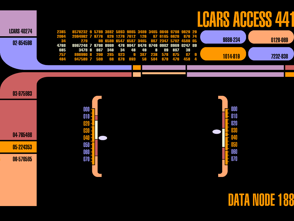
I tinkered quite a bit with trying to make it work before I hit the limit of my abilities and my willingness to spend more time on it. I put the idea aside with the thought that if in the future I am still crazy about changing the visuals of the screen, I always can. I just felt I was not investing my time in the right place anymore.
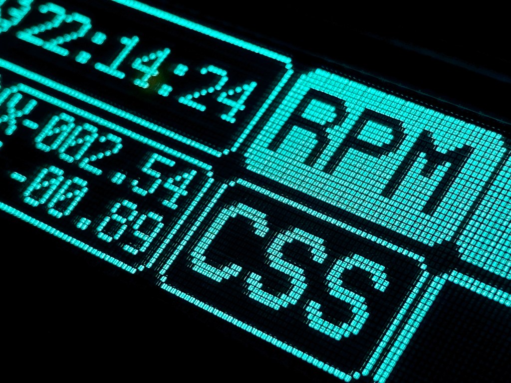
Goodbye LCARS, hello best effort. In the spirit of „better done than perfect“, the goal was now simply to display the information I needed in a design that was acceptable and achievable using only standard elements. I found a website that was thoughtfully designed and made the process delightfully practical. Lopaka is a “UI graphics editor for embedded screens with pixel perfect code builder and export”. The tool can be used for free and lets you build the screen in a graphical manner. It feels a bit like making a powerpoint slide. One of the many useful features is the code builder: whatever you draw on the screen is converted to code in real time and can be copied into your program. There is also a small library of symbols and if that’s not enough, images can be imported, edited and inserted. Good stuff!
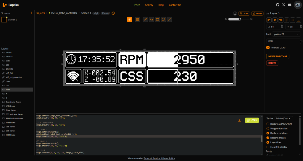
Getting the design from Lopaka onto the actual screen was no trouble at all and worked instantly.
RPM Sensor
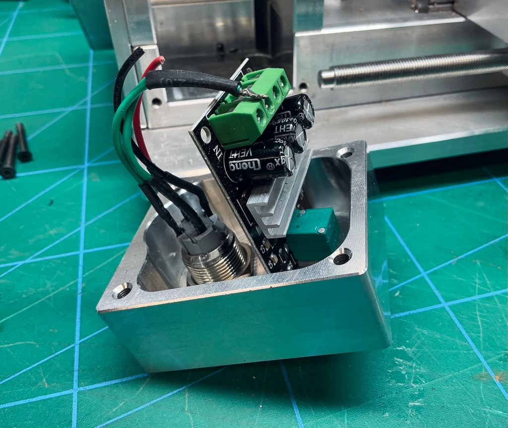
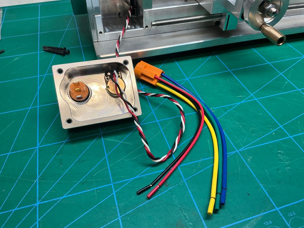
Great, now let‘s leave the whole display business aside and move on to other topics. I am not just building a nice home for the lathe, I am also modifying the lathe itself. The data to be displayed needs to come from somewhere and one such source is the RPM sensor. The first sensor I bought was not only a fail in terms of its own screen refresh rate, it was also too big to fit underneath the belt cover.
Granted, the replacement needed to be chopped up as well, but it was a decent solution.
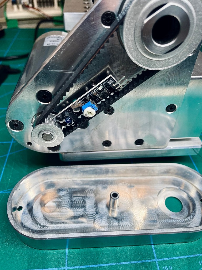
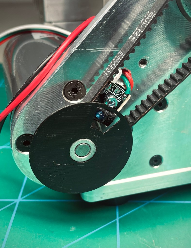
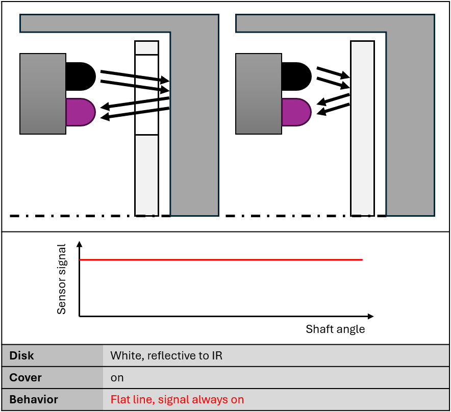
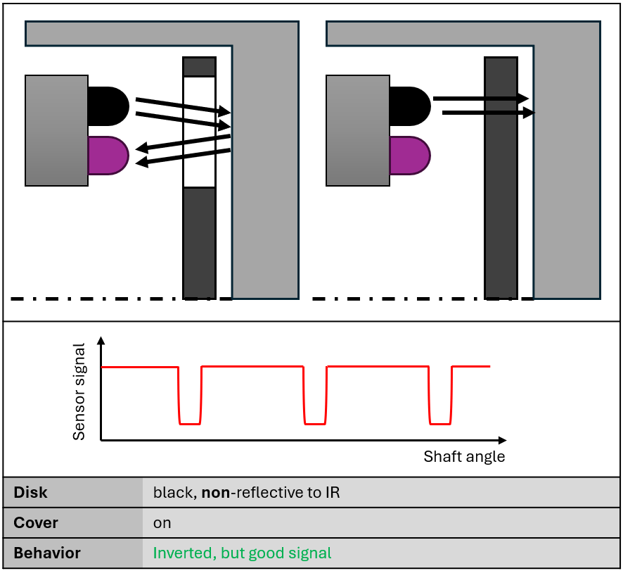
Unlike the first sensor which was sensing a passing magnet, this is an optical sensor which transmits infrared light and reads the reflected portion of the light. A gated disk was printed with black PLA and glued onto the motor pulley. A quick check to confirm its operation… not confirmed:( No signal at all. What was going on? The sensor did not react at all to the gate in the black disk, no matter what distance adjustments I made. It turned out that the disk was absorbing all of the IR light and not reflecting anything back.
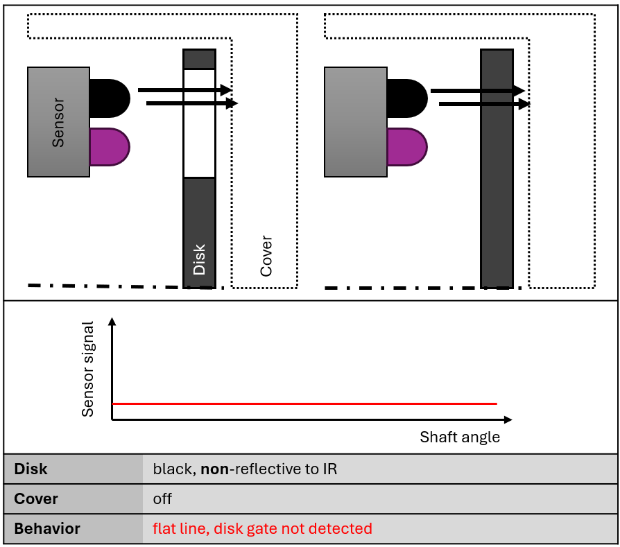
Not to worry, I have tons of other filament and just printed the thing in white. This time it worked, the sensor picked up the change in reflectivity when the gate passed in front of it.
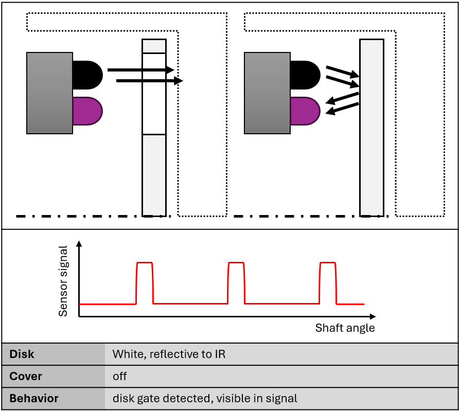
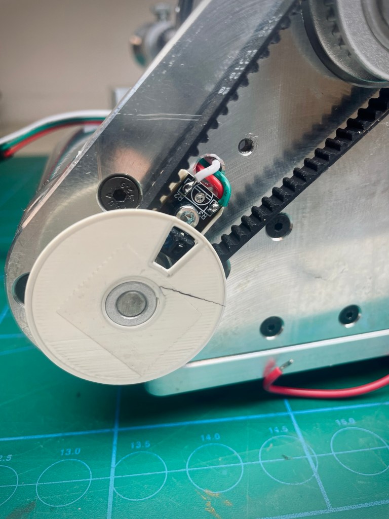
Juuust to mount the cover back on and Bob‘s my unc… huh? Now the sensor is on all the time. What gives? Well, because of the very limited space underneath the cover, the disk is almost in contact with it. Thus, for the sensor the distance between disk and cover is almost the same and cannot be distinguished. It’s always on. So what I confirmed as „working“ was not in representative conditions.
Frustrated with my lack of planning and foresight for this situation, I put it aside for a couple of days. A colleague at work is following my build with interest and asked about progress. I told him about the sensor issue and he gave me the right clue (thanks J.E.!): So the cover is reflective and the black disk isn‘t? Then just mount the black disk again. Of course, why did I not think of that? In this configuration it worked without issue.
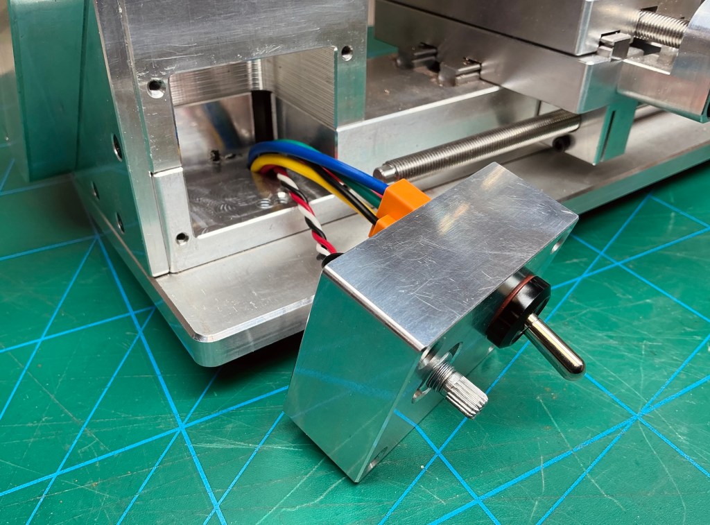
Speed Control and Spindle Switch
There is a saying in German „Erstens kommt es anders, zweitens als man denkt“, probably best translated as „First, things turn out differently; second, than you think“. It is quite true for this project and here is one example.
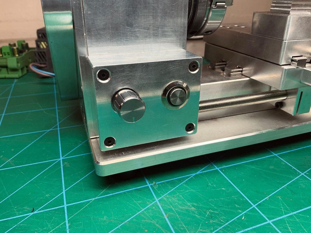
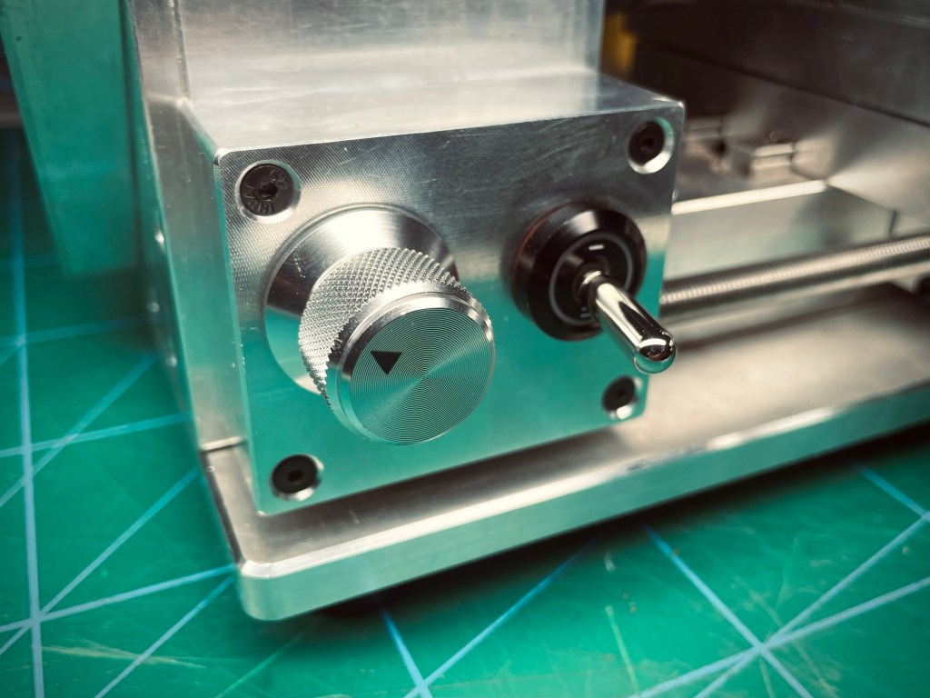
At the beginning my plan was to centralize all controls in one spot* on an instrument panel with the two displays (DRO and VFD) and all the knobs and switches. The lathe comes with a speed control knob and a pushbutton for the spindle motor, located in a housing/cutout on the lower left-hand side. Like I said, I wanted to relocate them to the central instrument panel and plug the holes in the original location. However, I found that (1) it is such a natural position for these controls and (2) my replacement parts fit perfectly with only minor modifications. So I kept those two controls where they were.
*Except for the light control, this one I wanted to keep on top next to the light.
Reflections
My first test of the RPM sensor „worked“, but didn‘t. You can test anything you want until the cows come home, but the results are meaningless if there was no hypothesis to test.
Another good practice is to test in small steps. Instead of wiring and assembling everything in one go and trying to locate errors at the very end, I progressed well in checking small things as I went along. For example when wiring the poti, it didn‘t hurt to quickly check the correct pin functions and then soldering the wires. Or when designing the screen layout, I first checked if the WiFi symbol animation worked before I hooked it up to the actual WiFi status. It just saves a lot of trouble.
I found it very interesting to think about different indicator and control philosophies, or the „ergonomics of human-system interaction“, as the ISO 9241 standard so eloquently puts it.
The „simple“ choice of which color the indicator light in spindle motor switch shall have opens up an entire world. Think about this: What do you actually want to show with this light?
- The intention could be hazard-centric. So emphasis is on risk, not function. In that case the light should be red and turned on when the spindle is running.
- The focus could be on status. In that case the light could be green, indicating that the spindle is running nominally.
- A state-change-centric philosophy would be to have the light flash when the spindle is turned on, then settle to a neutral or dim state.
Similarly for controls, consider some of these:
- Functional proximity. Placing controls near what they affect, light switch near the switch, spindle control switch near the spindle (like I did).
- Operator-centric. All controls in one place, less movement necessary for machine operation, efficient.
There are more philosophies than the above and depending on the complexity or importance of the system, it can make sense to carefully study all of those. For this project it does not matter all that much, it was just interesting to discover.
Resources
Links, references, or documentation that helped during the project or could be helpful to others.
- Lopaka GUI designer
Have you tried something similar? Got tips or questions? Feel free to leave a comment below.

Leave a comment