Turning Metal, Turning Habits
9 min read
It finally happened: I have a lathe! This is a machine tool I have always wanted to own and work with. Somehow it just never happened. Workshop space limitations, power outlet restrictions, money, priorities, etc. Even when launching into a huge development project, significantly expanding my workshop capabilities with a hefty CNC mill, I would have preferred to have a lathe. No regrets though, I still think a mill is much more versatile than a lathe.
Now the dream has come true*. And of course before even using it for the first time, I want to upgrade the hell out of it.
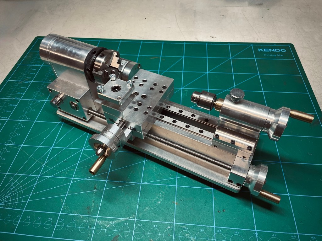
*partially. The lathe I bought will help in making parts but due to its very small size the range of applications is noticeably limited. I may just have to buy another lathe at some point… I have no other choice. You see that, right?
Goal
The goal is to significantly upgrade the lathe:
- Add a two axis DRO (digital readout)
- Add a spindle speed controller with two modes, RPM and constant surface speed (CSS)
- Display RPM / surface speed and other useful information
- Use an ESP32 for processing
- Build an enclosure with lighting to collect chips and contain the mess
- Allow for a possible future upgrade to CNC, or at minimum avoid hindering such an upgrade.
In addition to the goals above, I want to make this an example project with proper planning in the sense that I start buying parts only once the planning is done and to start building only once all the parts are in.
Often when I experience frustration in a project it is due to one of the above. Buying parts before I have the full picture can result in having to buy parts again and waiting for them to arrive, sometimes wasting a planned work session. Building before having all the parts is in part about instant gratification, the frustration then comes when I‘m in the flow and having to stop because of missing parts (I should not be too absolute here; if a project is complex enough it can make sense to get going in one area).
Another goal (yes, big project) is to learn about ESP32 microcontrollers. I highly enjoy novelty in all my projects and I often choose those where I can learn something new. I am very familiar with the Atmel mega and tiny line of controllers but have never worked with anything else. I am very curious about more powerful micros like the ESP32.
In this ideation phase I cannot hold back with ideas. While those are not part of this project, I keep them in the back of my mind:
- Quick-change toolpost
- Collet Chuck
- Coolant or mist lubrication system
- Microscope
- Electronic Leadscrew for cutting threads
- Milling attachment and spindle indexing
- CNC upgrade
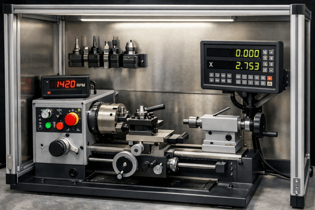
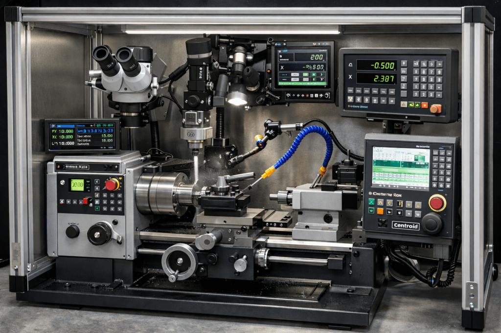
The ultra-lathe would look like this (according to ChatGPT):
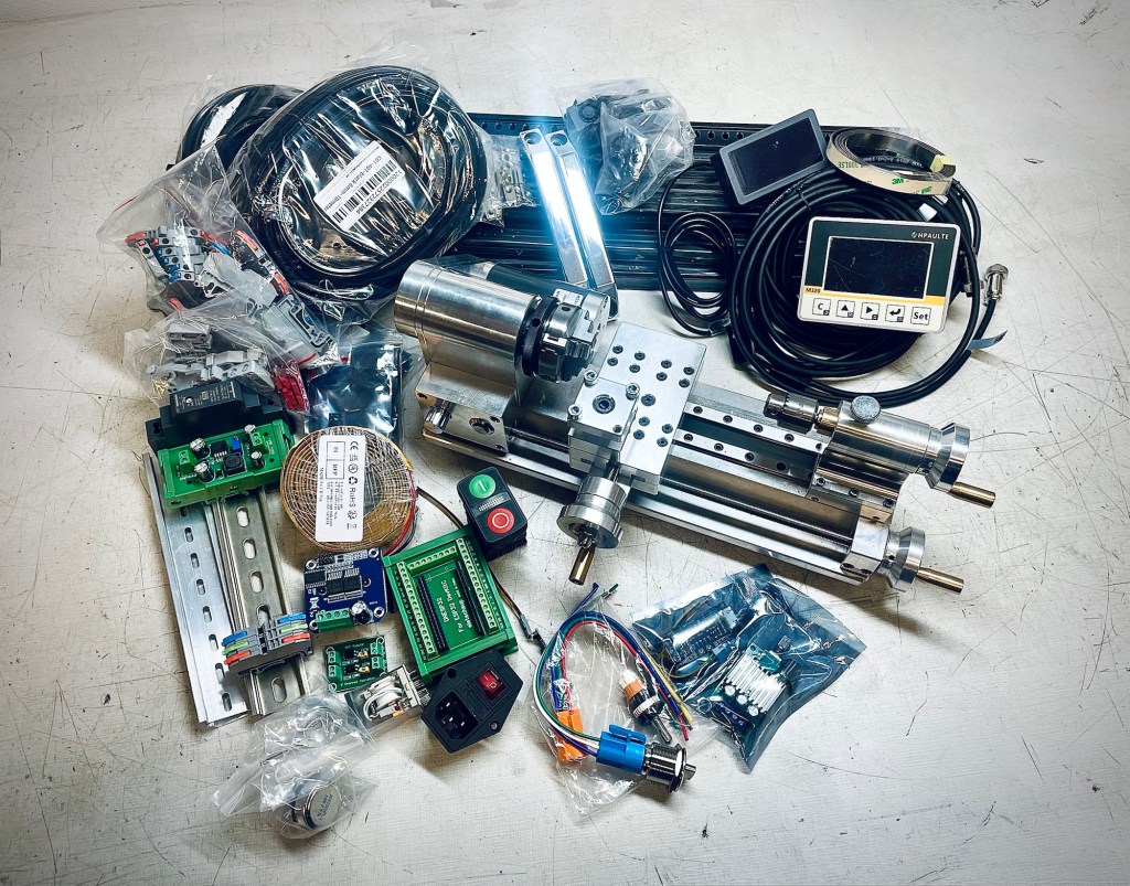
Materials & Tools
- Lathe, duh
- Enclosure & accessories like handles, rubber feet, nuts. I chose 2020 aluminum extrusion profiles and the sides will be filled with panels
- 2 axis DRO. I picked a unit with a small display
- RPM sensor
- ESP32 microcontroller
- Display
- Various electrical components like switches, knobs, converters, logic level shifters, power supplies
Process
In true product development fashion I started with a list of requirements that my build should satisfy. A list of controls dictated how I want to interact with the machine and another list gave me an overview of what information I want to see from the system.
| Control | Function Description |
|---|---|
| Main switch | Switches the system power on and off |
| Spindle on/off | Switches the spindle motor on and off |
| Speed control mode | Switch to choose between RPM mode and CSS mode |
| Speed adjustment | Adjusts the spindle speed (RPM or CSS setpoint, depending on selected mode) |
| Brightness control | Adjusts the intensity of the LED lights |
| (DRO controls) | (Operated via the DRO‘s dedicated controls) |
The list of where information is displayed was needed initially when the idea was to have individual gauges for RPM/CSS and their setpoints, LED indicators for mode, etc. After escaping a rabbit hole of thought which would have ended in more side quests like making even the gauges myself, I decided to just show all the necessary information on a screen. I negotiated with myself: I was not going to make my own gauges but instead I would buy a really cool display. Deal!:) (foreshadowing of the outcome of the „buying the parts only once planning is done“-plan…)
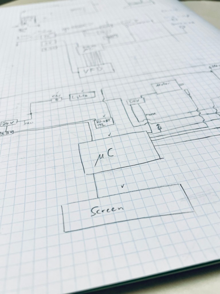
With the list of controls the electrical layout was made. Not yet with individual pin assignments, for now it was okay just to show device connections. The layout helped with identifying components and once the layout was solid, I started hunting down parts. I am glad I had the layout at hand and did not just order parts from Ali willy-nilly. I‘m sure I would have ordered the wrong switches for example. Take the spindle switch. Do I want it to only switch the power to the spindle or do I also want to indicate its state to the microcontroller? In the first case a SPST switch does the trick, in the second at least a DPST is needed.
Once I felt the layout was in a good state I ordered parts…. Okay I have to make one confession. I found a VFD screen with a decent interface at an okay-ish price. I had to have it! You understand, right? Just like I always wanted to have a lathe, I had always wanted to work with VFD screens. On my list of screen-coolness VFDs are on top (everyone keeps such a list in their mind, right? RIGHT???). Anyway, this one I just ordered mid-plan with minimal checks about compatibility, power requirements, interface definitions. I was so excited that I just accepted whatever extra effort I would have to spend to make it work.
Challenges & Learnings
Adherence to Goals
I want to change the way I do certain things and that is very hard. My standard project would normally start with a surge of excitement and creativity. It is an oh so satisfying rush, my head floods with ideas and solutions, it‘s like a drug. In this state I will order a bunch of parts, the cool ones first. Then when the dust settles and parts arrive, the crash. I find out that certain things won‘t work like I thought or that I had ordered the wrong part. Motivation plummets. Maybe the excitement holds for half way into the project, but I abandon it unfinished. Absolutely zero motivation to see it through.
It‘s a bit like shopping addicts. They enjoy the rush of researching and hunting down their favorite product for a good price, buy it and then the excitement fades right around receiving and unpacking the item.
I don‘t want to start ordering things just off of ideas anymore, I‘d rather order them as the result of a plan. So how did it go with this project? Not too bad. Yes there was the screen-incident, but apart from that I am happy with myself.
DRO trials
The DRO is a cool device. You get two read heads, magnetic tape and a display/processing unit. I wanted to try it out as soon as I had the chance. I plugged in one of the read heads and scratched it across the magnetic strip… Nothing. The display acknowledged the presence of the magnetic strip, but gave error codes for both read heads. Strange, was it dead on arrival? Damn you, Ali! I did a factory reset which set it to single axis mode and this worked without issue. So the read head was fine, the cable was intact, the display was showing good readings, it was just in two axis mode where it did not work. Even when plugging in both read heads, I would get errors. Finally ChatGPT came to the rescue with the right hint: Both read heads had to be within range of the magnetic tape to work. Before you ask, yes I read the manual and no, this was not in there.
RPM Sensor
I don‘t think I can put this entirely under bad preparation and would book it as „shitty product“. The RPM sensor display turned out to have a horrendously low refresh rate. So low in fact that I am not going to use it at all (if you want a beautiful RPM sensor, let me know. I have one extra:). It updates only every second or so and I imagined it would show almost real time readings. This is the main reason I abandoned individual gauges for RPM and CSS and chose to combine all the information on a display.
Result
I end this post at the stage right before assembly. I have done the electrical layout, component selection and ordering of parts. Next will be setting up the code skeleton, programming some first functions and frame assembly.
Reflections
I think I should be careful about stressing too much about one-shot perfection. Most of the time even professional product development happens in cycles with iterations. Effort is spent in any case, either in planning the very last detail for the perfect product or in iterations of prototypes. The expectation to make something perfect on the first try is ridiculous. It makes me either not finish projects or not even getting started on them.
Another thought about unfinished projects. It‘s not like when motivation fades for a half-finished project that it‘s gone forever. It often comes back after a while. What‘s often interesting to see at that point is how little work is left to finish the project. When I abandon the project it feels like a ton of work is left to do, when I pick it up again I find that it‘s 90% done and I wonder how I can have such different perceptions of the same thing.
I think writing blog posts about my projects helps with structure and pulling through.
A case for VFDs Why do I get so excited about them? (1) They take me back to childhood times of the 80s and 90s when a lot of devices had those. (2) They have this special kind of glow other screen technologies don‘t have. (3) There is a tangible visual depth to them, if you look at them closely you can make out several layers. (4) There are wires, grids, sections and glowy stuff. And maybe not surprisingly, they are a bitch to operate. I have a knack for complications, maybe that’s why I find them so intriguing.
Consider the differences to a boring old LCD. An LCD usually operates at 3.3–5 V and therefore can be powered and controlled directly* from the microcontroller pins. A VFD on the other hand requires multiple higher voltages, often two or three:
- Filament (heater) voltage: Usually about 1–4 V, at relatively high current, to heat the cathode so it can emit electrons.
- Grid voltage: Typically around 10–30 V (relative to the filament) to control which digits or segments are active.
- Anode (segment) voltage: Also typically around 10–60 V (relative to the filament) to accelerate electrons toward the phosphor-coated segments so they glow.
If all of the above was not yet cool enough, they have fantastic brightness, contrast, viewing angle and temperature operating range. I won‘t go into the disadvantages, that would be a shitty case for VFDs:)
*Often LCDs are not directly driven by microcontrollers. For practical purposes there is usually a driver IC in between to simplify communication and to free up pins on the micro to do other things.
Resources
- Check out this YouTube video with amazing close-up shots of VFDs.
Have you tried something similar? Got tips or questions? Feel free to leave a comment below.

Leave a comment