From Failure to Final Form
9 min read
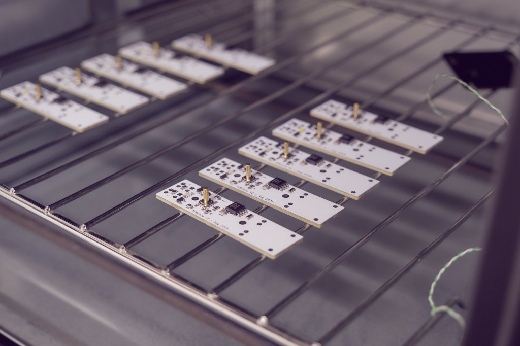
Right, let‘s do this again. This time the right way. I took out another board and components and remembered an old reflow oven I had won years ago at a company raffle. They had upgraded to a better one and gave it away to the employees. Nothing fancy actually, just a small pizza oven with a temperature sensor and a controller – but it works.
There was no stencil, so the solder paste was applied manually with a watchmaker‘s oiler. I do not mind soldering by hand, even SMD down to 0805 packages. But I have to admit I really enjoyed „baking“ a circuit board. Components on the bottom side, the USB charging circuit and the battery still had to be hand soldered, though.
Case Design
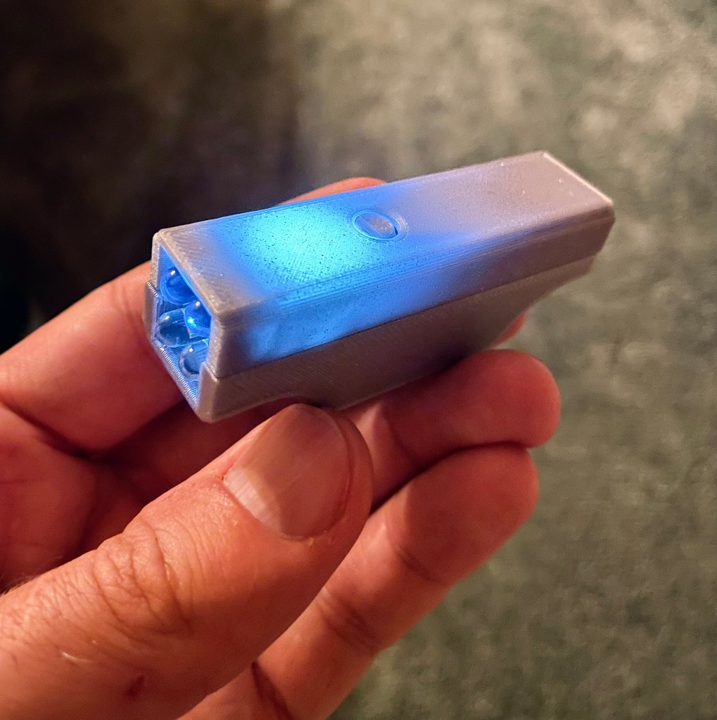
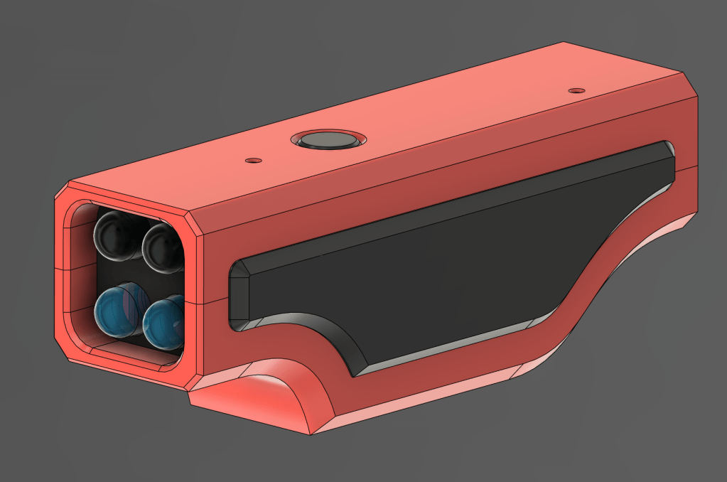
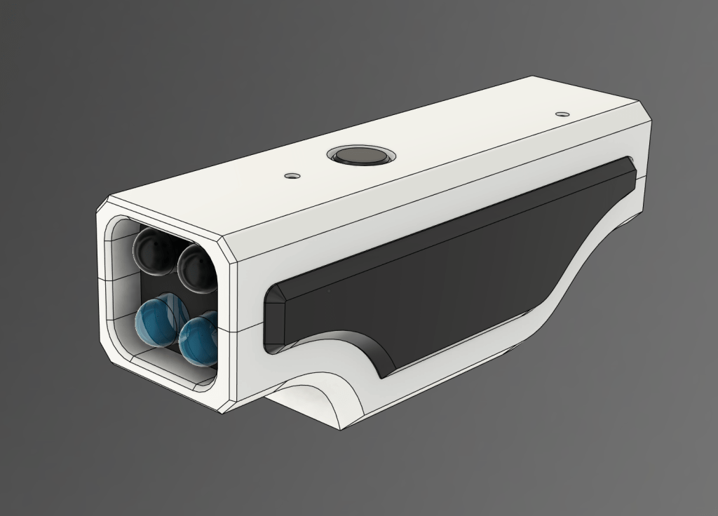
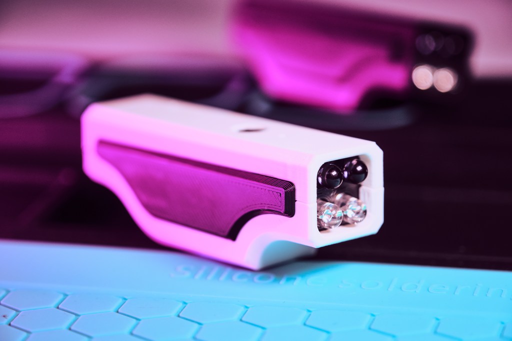
It was time to turn to the case design. I broke out the trusty Fusion 360 and got to work. It took a couple of iterations to get to a satisfying result. One thing I noticed was the brightness of the status LED was WAY too high. Not only did it show through the front of the device, it was even visible through the case. Stealth is different.
Again I had rushed the design a bit because I really wanted to just put the board in a case and try it. I ignored the thought saying „How you gon close it up? Hmmm??“. With tape, dangit! I was so close to the target, I couldn’t hold back. So with a taped-up, stroboscopic reissue of the TV killer, I went on a first hunt. And it worked! What joy, what juvenile fun:)
Still, I want to push myself to see projects to a clean end. Too many projects I have abandoned even at 90% completion. So I went once more back to the drawing board to solve the question of how to shut the case. It is as small as I could make it given the size of the circuit board. I did not want to make it any bigger with features for screws, snap latches or anything else. But those are all solutions allowing opening and closing of the case. Because of the built-in Li-ion cell and USB charging, there was no need to design it for access at all. I designed it to be glued shut.
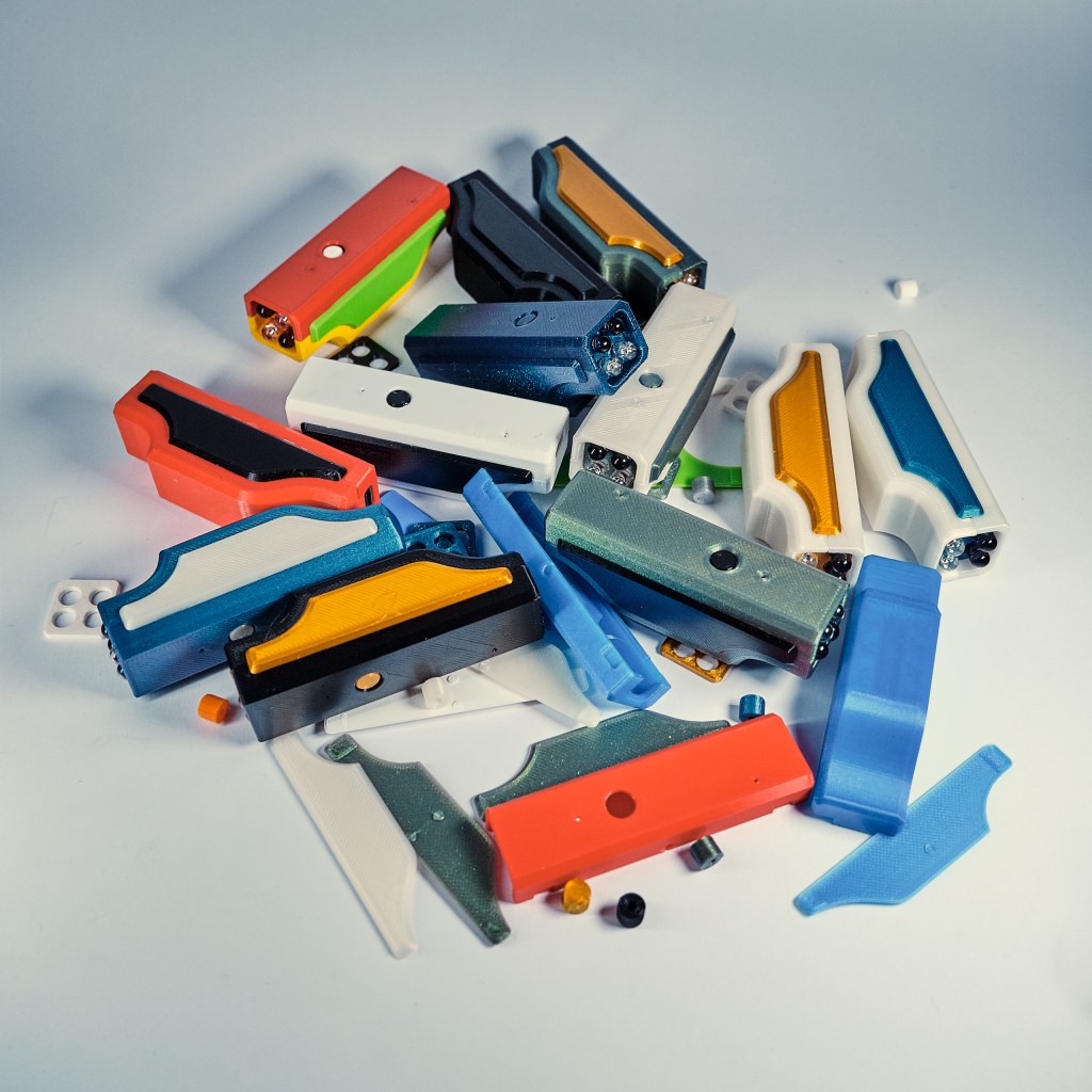
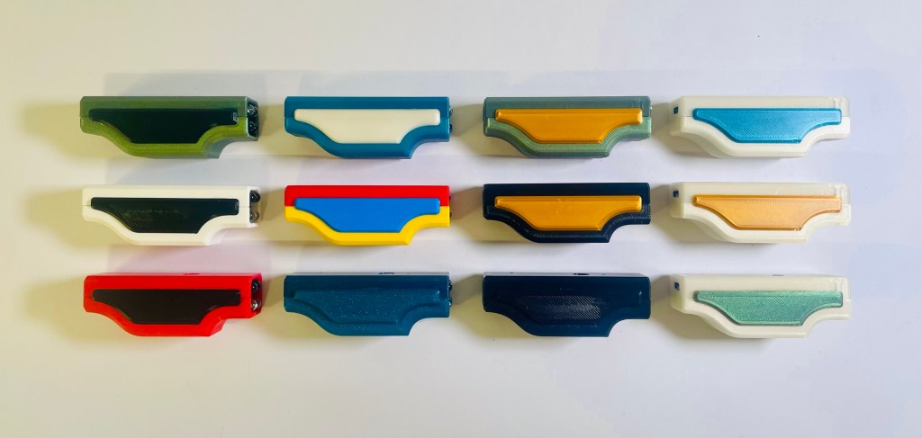
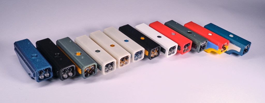
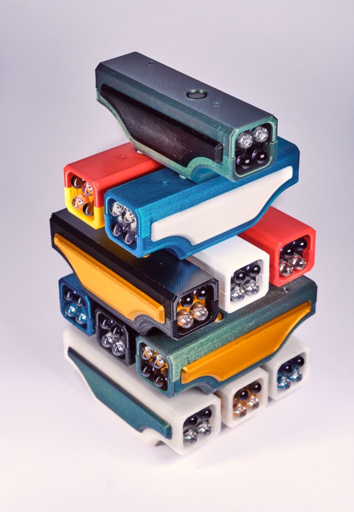
As someone with a 3D printer, a core belief is that there is no such thing as „I have enough filament“. From the Gridfinity project I had five base colors, from regular everyday printing I had black, white, gray and some others. Still, this selection seemed a bit boring to make 10 unique cases. I got a couple spools of some fancier filament.
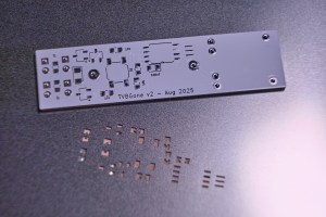
PCB v2
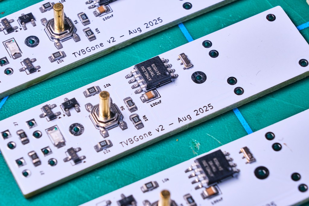
When I started the project I ordered parts to make 10 with the thought to give them away to friends and family. I got the first unit to work but was not going to go through the trouble of the same enamel wire hot fix with the remaining units. PCB design is just too easy and affordable for this. So the board designer was fired up again to fix the error, along with other small improvements. During soldering I noticed how helpful silkscreen information can be. I had to go back to the schematic often to check which resistor value goes where (or to put in a battery without releasing magic smoke). Having this information on the board makes a lot more sense. Normally it already is, I had removed it to get a cleaner look of the board. Since no one is ever going to see it anyway, back came the numbers.
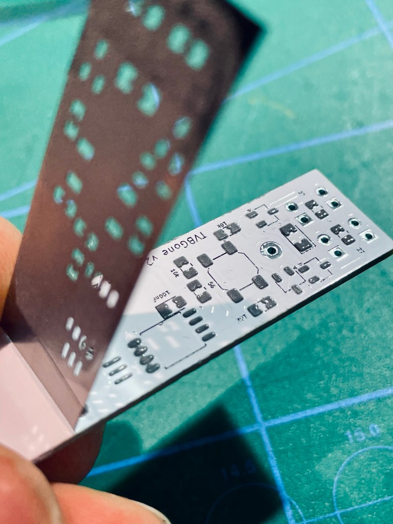
Another new thing I wanted to try was a stencil. I had never worked with one and it was not a lot of additional cost to get it as part of the PCB order.
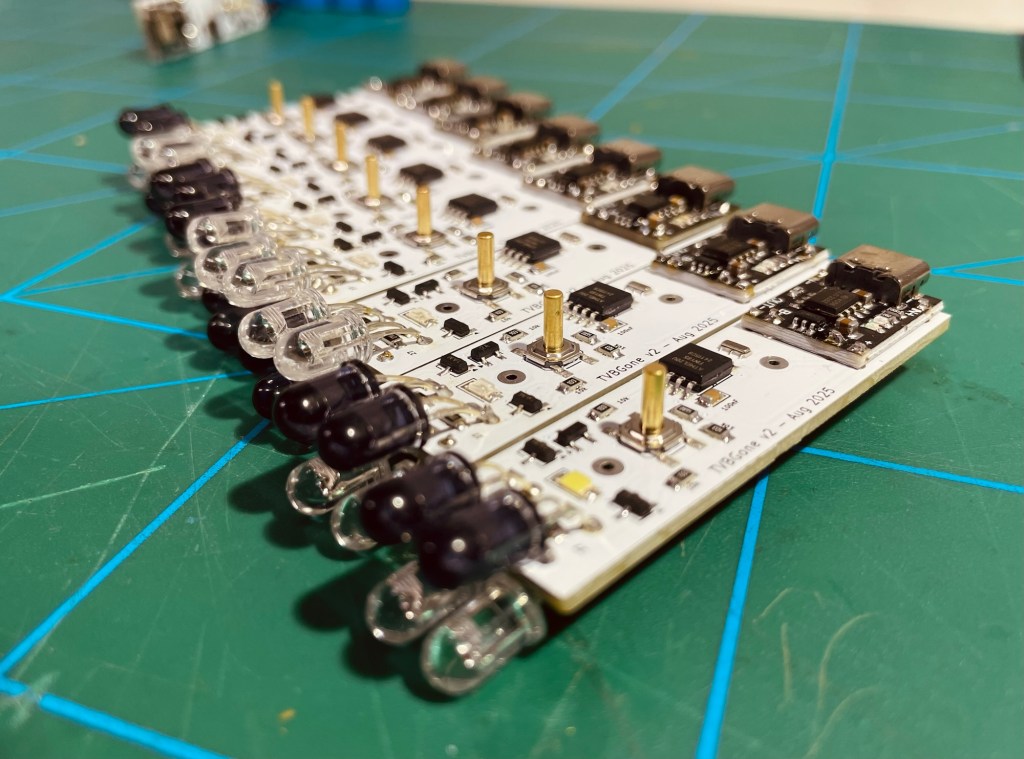
Finishing All Units
Getting the first one to work properly was important to be able to make an entire batch. Troubleshooting takes a long time on a single unit already, I wanted to be sure of not having to do any fixing on 10 units at once. That would be a disaster.
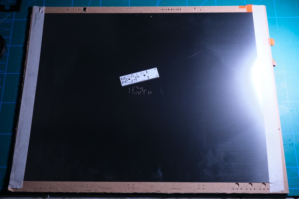
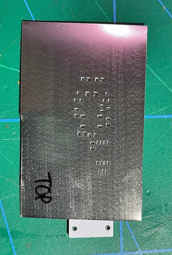
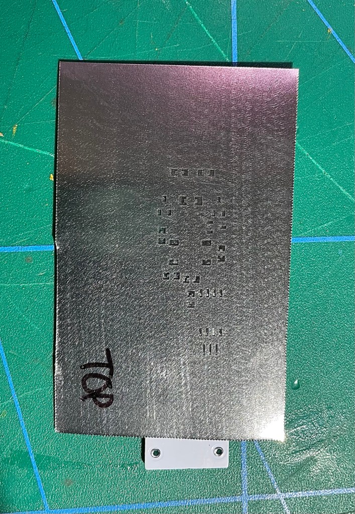
There was a funny surprise with the solder paste stencil. All the holes were in the right place and it was going to do its job, all fine there.
The surprise was its size. Compared to the tiny PCB, the stencil is huge. I wonder how this is done normally, if there are standard sizes for stencils and what machines they go into.
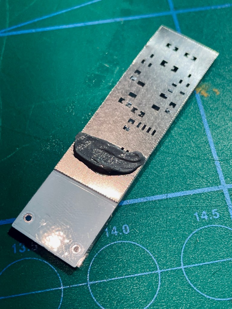
I cut and trimmed the stencil to the size I needed and tried to squeegee solder paste onto it. It worked quite well.
There were still a couple of components to be soldered by hand. Not too many, just the front LEDs, the underside components, the USB charging circuit and the battery cell. But multiplied by 10 made for some full work sessions.
Challenges & Learnings
Though simple on the surface, this project had many lessons in stock for me. Here are some of them.
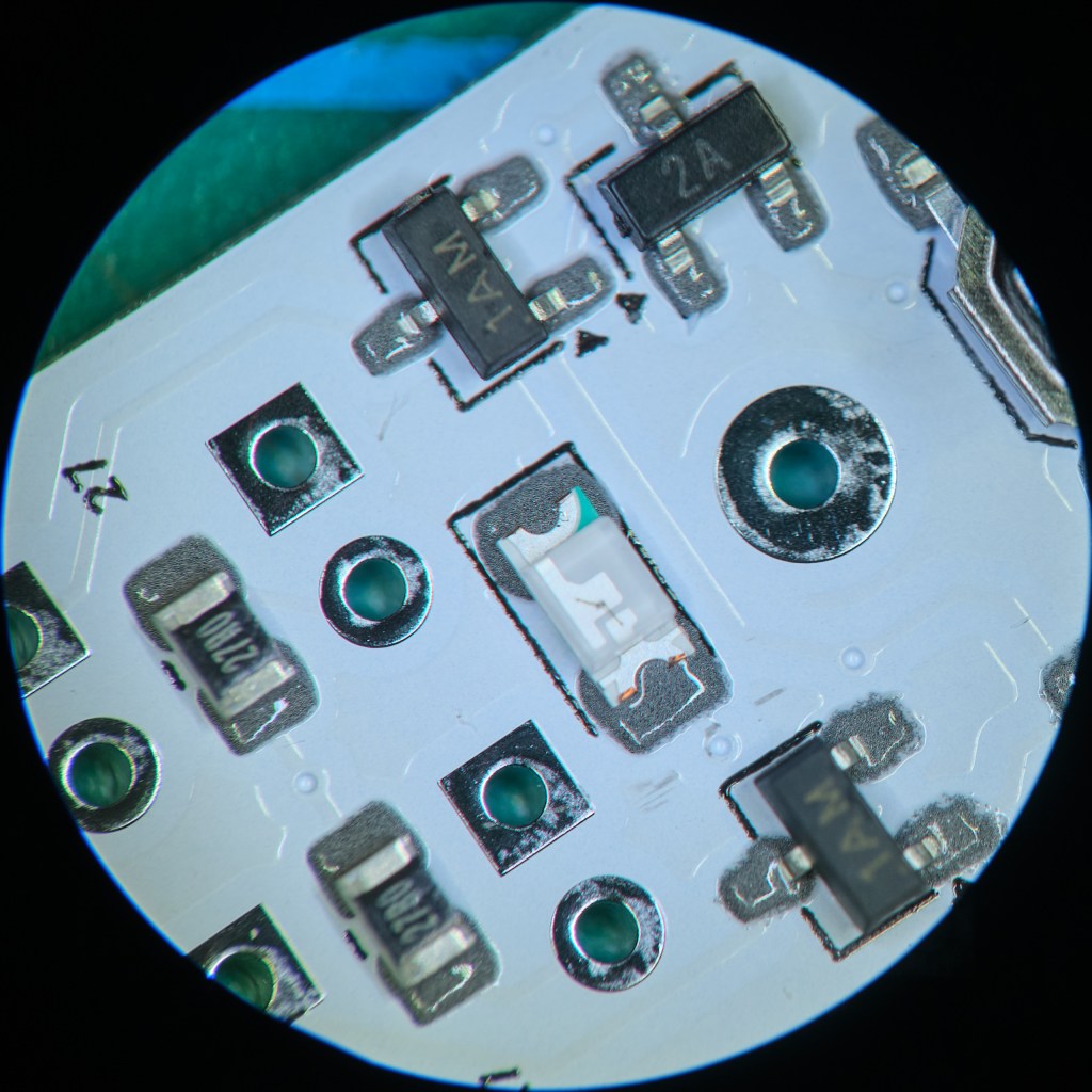
- Study the frikkin‘ schematic CLOSELY, print a BOM. I had not noticed there are not 5 identical transistors, but 1 and 4 in the schematic… No wonder nothing worked when I soldered everything together. Had I not had the right part in stock, this blunder would have meant a 2 week wait for Ali parts.
- ChatGPT was of great help with programming and troubleshooting. Whilst it is a stunning tool that overall helps tremendously, I sometimes fell into the trap of trusting it too much. I would blindly follow its instructions without questioning their validity and sometimes ended up wasting a lot of time on either complicated routes or factually wrong information. AI is strong in searching for information, but it is also strong in presenting information convincingly even if it is wrong.
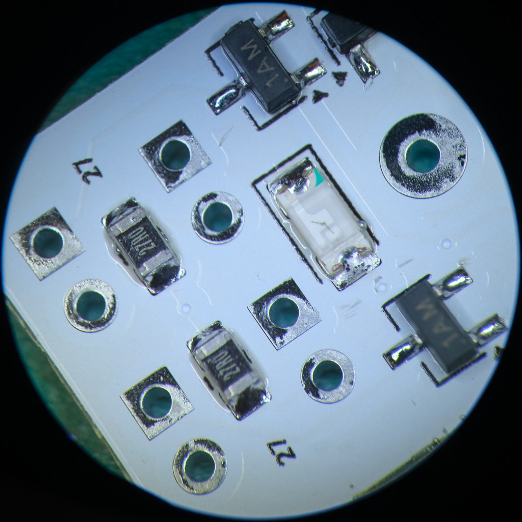
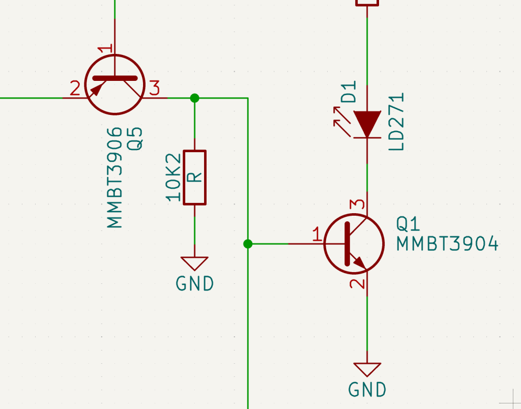
- I got so frustrated when my circuit just would not work. The programmed microcontroller did it‘s job on the breadboard, but not on the board. What the hell was going on? I probed it with the oscilloscope. It showed the chip was doing something but not my circuit. My girlfriend asked me if I had double checked the layout, „Yes I have“. Guess what – turns out I had made a mistake in the layout… See if you can spot it.
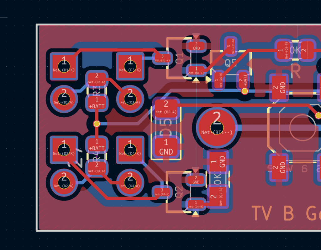
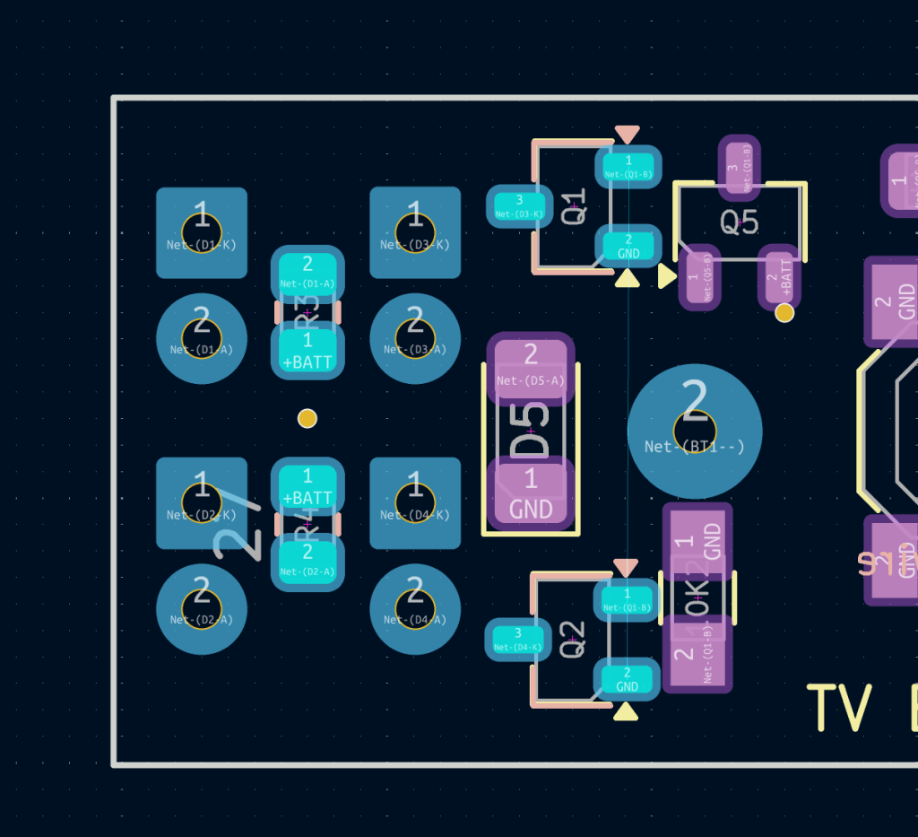
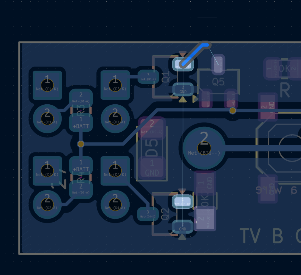
The signal from the microcontroller was not reaching the transistors, so it‘s obvious why there was no output at the front. To test if the rest works and if it was the only layout mistake, I fixed it with enameled copper wire.
- It pays off to add some margin in the parts order. Especially since most electronic components are quite cheap. I had planned to make 10 units to hand out to friends. With burning the first unit and wrecking an oscillator while assembling it, I did not have all the necessary parts anymore to make the full set of 10.
- Reflow soldering is easier than I thought. It is not much more (speaking as a hobbyist here, I am sure it is a science in itself) than smearing solder paste, sprinkling components on top and putting it in the oven. I will use this technique in the future for larger SMD projects.
- In the end my version of TV-B-Gone is a mashup of zookzook’s and adafruit‘s schematics and codes. I took aspects of each. Somehow zookzook‘s code was not able to turn off LG TVs. I programmed a unit with adafruit code and my LG TV reacted. Even though I did not understand the difference – ChatGPT told me the world code files were indentical – I was not going to spend time getting to the bottom of it.
- Learning a lesson and not implementing it next time around means it was not learned. Again in revision 2 of the PCB I forgot to add silkscreen markings for battery polarity. The very thing that fried the first board…
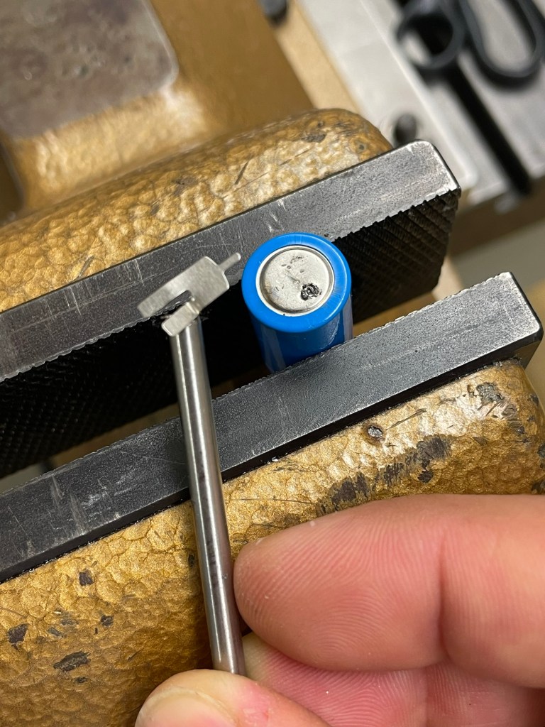
- Welding the battery tabs on the cells took some tries. I had access to a spot welding machine at work but for some reason it was really good at welding the tab to the stick itself but not the battery. It was also a bit too clunky for those small cells. I remembered seeing something similar on Ali and searched for it again. It was like $10 – totally worth a try. The device has to be put on the highest setting for a solid weld, it‘s not exactly overpowered. But it got the job done. In between the first fail and receiving the Ali-spot welder I tried soldering the tabs. This worked but I think spot welding is the more suitable method.
Result
Reflections
This project was purely for the fun of reviving an old prank device. In the process I had a chance to refresh rusty electronic skills – it had been a long time since the last project involving PCBs and microcontrollers.
Another satisfying process I observed when making the case. I felt the project was more or less done after I had soldered everything and the circuit worked. Having to sit down to figure out the case felt like extra work, so I cobbled something together just to have it done. But as I spent more time on the design, the enjoyment crept back in, and I started doing it properly. By the end, I actually really liked how it looked.
Something I rarely do is working with larger numbers. Normally my projects are one-off prototypes. I actually quite enjoyed getting everything ready, having all parts in place and a prototype tested before starting the „big“ batch work.
Carrying a universal remote turns waiting at bus stops or train stations into a sport. Where’s the next TV? The thrill is in trying to switch one off while it’s in use — and not getting caught. It’s harmless fun… unless the World Championship is on.
Resources
- SMD TV-B-Gone by zookzook
- Adafruit TV-B-Gone Kit
- JLCPCB – PCB manufacturing service
- Commercial TV-B-Gone
Have you tried something similar? Got tips or questions? Feel free to leave a comment below.

Leave a comment